The Padlock Is Only the Beginning: Isolation Evidence That Stands Up to Challenge
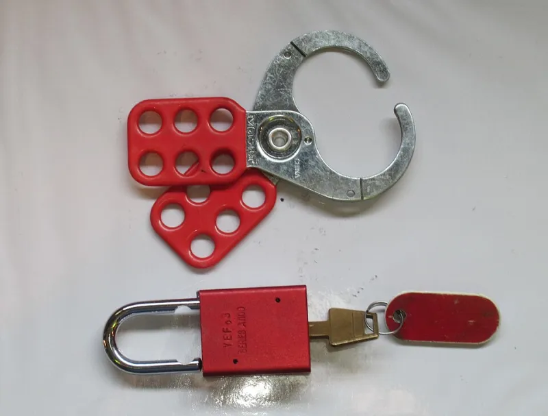
Photo: Wtshymanski, CC BY-SA 4.0, via Wikimedia Commons
Isolation evidence is often judged by what can be seen in a folder: a photograph of a padlocked isolator, a completed tag, a signed permit. Each has a place, but none of them proves that the equipment being worked on is dead. A photograph records appearance at a moment in time. It does not record the absence of energy at the point of work, the identity of the circuit, the condition of the label or the possibility of a backfeed. For UK plant teams, the difference matters because false confidence in isolation is more dangerous than an obvious gap in procedure.
At Apex Engineering Services, we see this most often where isolation points are shared, labels have drifted from drawings, or evidence packs have become a collection of images rather than a chain of proof. The purpose of this article is not to restate the well-known requirement to lock off. It is to set out a short verification sequence that supervisors can use to challenge isolation evidence before work starts, and again at close-out.
Why a photograph proves less than it appears
A photograph of an isolator can show that a lock is fitted and a tag is present. It cannot show whether the correct isolator was selected, whether the circuit is fed from more than one source, whether the test was taken at the work point, or whether the tester was proved before and after use. It also cannot show whether the isolator is shared with other equipment, or whether someone else has authority to remove the lock under a group procedure.
This is not an argument against photographs. They are useful supporting evidence, particularly where they show a test point, a label, a cable marker or a discrepancy. The problem arises when the photograph becomes the primary proof. A supervisor should be able to ask what was tested, where, by whom, with which instrument, and what the result was. If the answer is simply that the image shows a lock, the evidence is not complete.
Start with the boundary, not the padlock
Before any lock is applied, the isolation boundary should be agreed. That means defining the work scope and listing every source of energy that could affect it: electrical supply, stored pressure, hydraulic pressure, steam or hot water, gravity, spring tension, pneumatic control air and any automatic or remote starting arrangement. The isolation schedule should identify each point and link it to a unique isolation ID within the work pack.
For shared isolation points, the boundary is especially important. An isolator may feed several circuits or items of plant. Locking it may remove supply from equipment outside the work scope, or it may leave a parallel supply in place. The isolation schedule should record who else is affected and how their work is controlled. A group lock box, with a clear list of all tasks relying on the same isolation, is often more defensible than a single padlock and a handwritten tag.
A five-step verification sequence
First, confirm the point at the equipment. Compare the field label with the current drawing, panel schedule, cable core markers and, where available, the P&ID or single-line diagram. If the label and drawing disagree, stop and record the discrepancy. Do not assume that the drawing is right because it is the latest revision, and do not assume that the label is right because it is physically present.
Second, apply the lock and tag under control. Record the unique isolation ID, the time, the person applying it and the work pack it supports. For shared points, record the other tasks and personnel affected. The tag should identify the isolation, not just the person. A tag that says only a name is difficult to challenge later.
Third, prove the tester and test at the point of work. Use an approved voltage detector suitable for the system, with a proving unit check before and after the test. For pressure systems, use a calibrated gauge and a controlled bleed. Record the instrument serial number and calibration date. Test at the point of work, not only at the isolator. For electrical work, test all relevant combinations of conductors, including phase-to-phase, phase-to-neutral and phase-to-earth. For control systems, consider backfeeds from uninterruptible supplies, generators or external signals.
Fourth, prove the absence of stored energy. Where it is safe to do so, attempt start or confirm that stored energy has been released, blocked or restrained. This may include bleeding pressure, chocking moving parts, releasing springs or confirming that gravity cannot cause movement. The exact method should be recorded, not assumed.
Fifth, close out with evidence that can be reviewed. The close-out pack should include the isolation schedule, test results, instrument records, proving unit checks, photographs of test points and labels, discrepancy notes and sign-off by the competent person and supervisor. The photograph should support the test record, not replace it.
Legacy drawings and labels: the weak link
On older UK sites, drawings are often a record of what was intended at the last modification, not what exists today. Field labels can be altered, replaced or copied from a neighbouring panel. A padlock on a mislabelled isolator is still a padlock on the wrong point. Before isolation, the team should check whether the drawing has been verified against the field within a defined period, and whether any recent modifications have been captured.
Where confidence is low, the isolation plan should say so. A drawing confidence field in the permit, completed by the competent person, gives the supervisor something to challenge. It also prompts the team to trace, label or record temporary identification before the work begins rather than discovering the problem after the lock is fitted.
Questions a supervisor should ask
A useful challenge is not adversarial. It is a check that the evidence chain is complete. Supervisors should ask: can you show me the test at the point of work? How did you confirm that the label matches the drawing? What backfeed paths did you consider? Who else relies on this isolator? What changed since the drawing was last verified? If the answers rely on the photograph alone, the isolation evidence is not yet defensible.
In 2026, with ageing plant and constrained maintenance windows, the temptation to treat a photograph as proof is understandable. It is also avoidable. Isolation is a process of proving, not a collection of artefacts. The padlock is only the beginning.